How to Know When an Industrial Component Is About to Fail
Industrial automation components rarely fail without warning. In most cases, the failure is preceded by days, weeks, or even months of increasingly detectable symptoms, error codes, performance changes, unusual sounds, heat, or communication faults. The difference between a planned maintenance swap and an unplanned production shutdown is almost always whether someone recognized and acted on those symptoms in time.
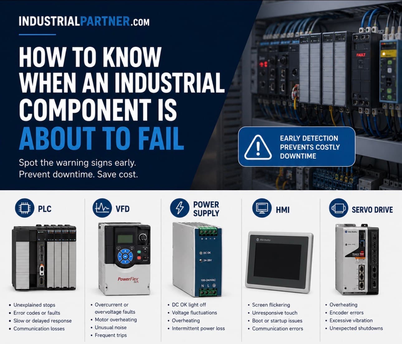
This guide covers the most important early warning signs across the five component types most responsible for unplanned industrial downtime: PLCs, variable frequency drives, industrial power supplies, HMI panels, and servo drives. For each, we explain what the early warning signs look like, what is typically causing them, and what to do when you see them.
Industrial Partner stocks genuine replacement PLCs, VFDs, power supplies, HMIs, servo drives, and I/O modules for fast emergency sourcing when warning signs become failures. Browse the catalog or contact the team.
Why Early Detection Changes Everything
The financial case for catching failure early is straightforward. A component that is replaced during a planned maintenance window — even at premium parts cost — costs a fraction of the same component failing mid-production. Research across manufacturing sectors consistently shows that unplanned downtime costs industrial facilities between $10,000 and $250,000 per hour depending on industry and process criticality.
Beyond the direct cost of lost production, a component failure during operation often causes cascading damage. A failed VFD that shuts down without controlled deceleration stresses mechanical couplings. A PLC that crashes mid-cycle leaves actuators in undefined states. A power supply that collapses suddenly can corrupt PLC program memory and damage downstream devices. Catching the warning signs prevents the failure itself — and prevents the secondary damage that often makes a straightforward repair into a major maintenance event.
Related: Why Manufacturing Downtime Costs More Than You Think.
PLC Failure Signs: What to Watch For
Programmable logic controllers are built for industrial reliability, but they are not immune to failure. The most common causes of PLC failure are power supply degradation (within the PLC itself), battery depletion, I/O module damage from field wiring faults, and — in older systems — component aging in the CPU circuit board itself.
1. Intermittent Fault Codes With No Clear Field Cause
When a PLC generates fault codes that cannot be traced to a specific field device or process condition — and that clear spontaneously or on power cycle — this pattern is one of the clearest early indicators of PLC hardware degradation. Random faults that come and go without process explanation are typically caused by internal memory errors, power supply ripple reaching the CPU, or connector oxidation on I/O module backplane connections.
Warning sign: Fault codes that self-clear on power cycle but recur without field cause. Investigate internal PLC power supply health and check module seating before assuming the field device is the problem.
2. Low Battery Warning
Most PLCs use a lithium battery to maintain program memory and real-time clock data during power outages. A low battery warning — flagged either by a dedicated LED on the CPU module or by a diagnostic alarm in the controller — gives advance notice before the battery reaches the point of failure. The consequence of an expired PLC battery during a mains power interruption is program loss, which can require hours of recovery work.
Best practice: replace PLC batteries immediately when the low-battery warning activates. Do not wait until the next scheduled maintenance window. Battery replacement takes minutes; program recovery can take hours.
3. Communication Faults to Specific I/O Modules
Repeated communication faults between the PLC CPU and specific I/O modules — while other modules in the same rack communicate normally — indicate that the affected module is failing. These faults are often thermal in origin: the module communicates correctly when cool but produces errors as it heats up during operation. A module that generates intermittent communication errors under normal operating temperatures is close to total failure.
4. Slow Scan Times or CPU Performance Degradation
Most PLCs provide diagnostic registers showing current scan time. A PLC whose scan time is increasing, particularly if no programming changes have been made, may be experiencing internal CPU issues, excessive diagnostic overhead from accumulating fault logs, or early-stage memory failure. Compare current scan time against the baseline scan time from the most recent commission to identify degradation.
5. Visible Hardware Damage
Physical inspection of PLC modules should be part of every routine maintenance check. Signs of imminent failure include:
Related: PLC Spare Parts: What Every Maintenance Manager Should Keep in Stock.
VFD Failure Symptoms: Catching Drive Problems Early
Variable frequency drives contain power electronics, capacitors, IGBTs, gate driver circuits, and cooling components, that operate under significant electrical and thermal stress in continuous industrial service. VFD failures are often predictable if the right warning signs are observed and acted on before the drive reaches the point of protective shutdown or catastrophic failure.
1. Increasing Output Current with Stable Load
If a VFD's output current is trending upward over time while the driven motor's mechanical load has not changed, this is a strong indicator of one of two developing problems: the motor's insulation is degrading (causing increased magnetizing current), or the VFD's output filter components are beginning to fail. Either condition, left unchecked, leads to an eventual drive trip or motor failure.
Warning sign: Rising output current on a stable load application over days or weeks. Log the drive's output current at a consistent operating point weekly and trend the data.
2. Drive Overtemperature Alarms
A VFD that generates overtemperature warnings at ambient temperatures that previously caused no thermal alarms has a cooling problem. The most common causes are a failing internal cooling fan (detectable by unusual noise or vibration from the fan), clogged heat sink fins from accumulated dust, or a blocked ventilation path in the panel where the drive is installed. An overtemperature VFD that is not corrected will eventually trip on thermal protection, and repeated thermal cycling accelerates degradation of the DC bus capacitors.
3. DC Bus Ripple and Capacitor Aging
The DC bus electrolytic capacitors inside a VFD have a finite service life — typically 60,000 to 100,000 hours at rated temperature, but significantly less if the drive runs hot. As capacitors age, DC bus ripple increases, output voltage regulation worsens, and the drive becomes more susceptible to nuisance trips on overvoltage and undervoltage. Some VFD diagnostics screens display DC bus voltage ripple directly; on drives without this display, increasing frequency of nuisance DC bus fault trips is the observable symptom.
4. Ground Fault Alarms Without Wiring Changes
A ground fault alarm that appears without any wiring changes to the motor cable or motor suggests developing insulation breakdown, either in the motor winding itself or in the output cable. This is a progressive fault: the first ground fault alarm is a warning; the next may be a drive shutdown. When a ground fault alarm appears on a previously fault-free circuit, perform a motor insulation resistance test (megger test) at the earliest opportunity.
5. Parameter Drift After Power Cycling
A VFD whose stored parameters change after a power cycle, settings that should be non-volatile appearing with altered values, has a memory fault, typically caused by failing non-volatile RAM or a depleted internal parameter backup battery. This is a serious warning sign: a drive that cannot retain its configuration reliably cannot be trusted to restart correctly after a power interruption.
Related: Variable Frequency Drive (VFD): Complete Buyer's Guide.
Industrial Power Supply Warning Signs
Industrial DIN-rail power supplies are one of the highest-failure-rate components in automation panels — yet they are among the most commonly overlooked in preventive maintenance programs. A degrading power supply rarely fails suddenly; it provides weeks or months of observable warning signs before collapsing completely.
1. Output Voltage Drift
A healthy 24VDC industrial power supply maintains output voltage within ±1% of rated value (23.76V to 24.24V) under all load conditions. A supply whose output is drifting toward the lower or upper edge of its regulation range — detectable with a calibrated DVM at the supply output terminals — is showing signs of internal component aging. Output voltages below 23V or above 25V are cause for immediate investigation and proactive replacement.
Action item: Measure 24VDC bus voltage at the power supply output terminals quarterly as part of routine panel maintenance. Record the readings and trend them. A healthy supply does not drift.
2. Increased Output Ripple
As a power supply's electrolytic capacitors age, the ripple on the DC output increases. This is not visible on a standard DVM, it requires an oscilloscope or a power quality analyzer. Increased DC bus ripple causes PLC communication errors, HMI display noise, sensor signal instability, and false fault trips in servo drives. If a panel is experiencing unexplained intermittent faults across multiple devices simultaneously, check the 24VDC bus ripple before replacing individual devices.
3. Increasing Surface Temperature
A power supply running significantly hotter than it did during commissioning, detectable with a contact thermometer or thermal camera, is working harder than it should. Common causes are increased load (additional devices added to the same supply), reduced cooling airflow from a clogged panel filter, or internal component degradation causing reduced conversion efficiency. A supply running at its thermal limit is approaching end-of-life.
4. Audible Buzzing or Coil Whine
A power supply that emits audible buzzing, whistling, or high-frequency coil whine that was not previously present has an internal component operating abnormally. Coil saturation, inductor core issues, and failing filter capacitors all produce characteristic sounds. If the noise is intermittent or changes with load, the failure is progressing.
Related: Industrial Power Supply: Selection Guide, Failure Signs, and Replacement Sourcing.
HMI Failure Signs: Operator Interface Degradation
Human-machine interface panels fail in recognizable patterns. Because HMIs combine a display, a processor, a touchscreen, and a communication interface in a single unit, failure can manifest through any of these subsystems, but each produces distinct observable symptoms.
1. Display Darkening or Uneven Backlighting
Gradual darkening of the HMI display, or the appearance of darker patches, bright spots, or visible backlight bleed, indicates backlight degradation. In LED-backlit HMIs, individual LED strings begin to fail over time, producing characteristic uneven illumination. In older CCFL-backlit panels (common in early-2000s HMI hardware), the cold cathode fluorescent lamp has a finite service life that produces progressive darkening with age.
2. Touchscreen Calibration Drift
An HMI touchscreen that requires increasingly frequent recalibration, or where the active touch area no longer aligns correctly with the displayed button positions, has a degrading resistive touchscreen overlay. Resistive touchscreens wear at the edges and corners of their active area first, producing characteristic 'dead zone' behaviour in peripheral areas of the screen.
3. Communication Dropouts to PLC
An HMI that loses its communication connection to the PLC intermittently, producing 'Communications Error' messages that self-clear may have a failing communication module, corrupted communication parameters, or a degrading cable connection. When this fault occurs on a system that has operated without communication issues for years, suspect hardware rather than configuration: the physical communication interface on the HMI is the most likely fault location.
4. Slow Screen Refresh or Application Freezing
An HMI whose screen refresh is noticeably slower than normal, or whose application freezes periodically and requires restart, may be experiencing failing flash memory, RAM degradation, or in embedded Windows HMI platforms an accumulation of software issues that is masking underlying hardware faults. On embedded Windows panels, distinguish software from hardware by performing a clean image restore: if the performance problem persists after restore, the hardware is the cause.
Servo Drive Failure Signs: Motion System Warning Indicators
Servo drives control the position, velocity, and torque of servo motors with high precision. Because they are closed-loop systems with continuous feedback from motor encoders, servo drives can detect and report a wide range of developing mechanical and electrical problems before they cause a failure, but only if the maintenance team is monitoring the right parameters.
1. Following Error Increasing Over Time
Following error is the difference between the commanded motor position and the actual measured position at any point in time. A servo axis whose following error is trending upward , even if it has not yet generated a following error fault — is showing signs of a developing problem. Common causes include mechanical wear (gearbox backlash, ballscrew wear, bearing degradation), motor winding degradation, or servo gain parameters that have drifted out of optimal tuning due to mechanical changes.
Monitor: Log the peak following error for each servo axis during a standard production cycle weekly. A rising trend is a specific, actionable early warning of approaching axis failure.
2. Regeneration Resistor Overtemperature
Servo drives with regenerative braking resistors generate heat when the motor decelerates rapidly. A regeneration resistor that is running significantly hotter than normal, or that is triggering overtemperature alarms during deceleration cycles that previously caused no thermal issues, may indicate a failing braking resistor, a failing internal IGBT causing excessive regenerative current, or mechanical changes (increased system inertia) that are generating more regenerative energy than the resistor was sized for.
3. Encoder Fault Alarms
Encoder communication faults, particularly those that are intermittent and position-dependent — indicate encoder degradation, cable damage, or connector issues at the encoder-motor interface. The encoder cable on servo motors is a high-failure-rate component due to the continuous flexing it experiences in motion applications. An encoder fault that appears at specific axis positions but not others almost always points to a damaged cable that makes intermittent contact.
4. Audible Changes in Motor Operation
A servo motor that produces grinding, clicking, or unusual vibration sounds that were not previously present has a mechanical issue, most commonly bearing wear. Servo motors run at high speeds and bearing failure produces characteristic high-frequency vibration that can often be heard before it becomes detectable as a following error increase. Vibration analysis with a handheld accelerometer at the motor bearing locations will confirm developing bearing wear.
What to Do When You Detect Warning Signs
Detecting a warning sign is only the first step. The follow-through determines whether the warning prevents a failure or merely precedes one. The standard response sequence is:
Industrial Partner: When warning signs appear, we can provide same-day quotes for replacement PLCs, VFDs, power supplies, HMIs, and servo drives — so you source the replacement before the failure happens. Browse replacement components or contact the team.
Conclusion: The Competitive Advantage of Early Detection
The maintenance teams that consistently outperform on uptime are not those with the best emergency response capability , they are those who rarely need it. Early detection of industrial component failure signs transforms unplanned breakdowns into planned replacements, eliminates emergency procurement costs, prevents secondary equipment damage, and gives the maintenance team control over when and how repairs happen.
The warning signs covered in this guide, from PLC scan time drift and VFD capacitor aging to power supply voltage drift and servo following error trends — are all observable before failure with existing instrumentation and no specialized condition monitoring equipment. The starting point is building the habit of looking.
Industrial Partner stocks the full range of industrial automation replacement components — PLCs, VFDs, power supplies, HMIs, servo drives, I/O modules, and more — for fast sourcing when warning signs require action. Browse the catalog · Request a quote